Learn how to design different levels of high availability into your Kubernetes cluster and follow the instructions for implementing them
🎉 Kubecost 2.0 is here! Learn more about the massive new feature additions and predictive learning

Kubernetes High Availability: Tutorial & Instructions

Like this Article?

Subscribe to our Linkedin Newsletter to receive more educational content

Subscribe now

Kubernetes has massively disrupted ideas about infrastructure reliability, changing conversations - and calculations - around high availability for modern applications. But what about Kubernetes itself? How reliable is it, and how does it achieve reliability? How can its inherent reliability be leveled up to achieve high availability?

Is Kubernetes a distributed system that uses etcd because it is a distributed database, or is etcd being a distributed database what makes Kubernetes a distributed system? Fundamentally, Kubernetes high availability depends on high availability for its API. The API uses etcd as its backend key-value store, making etcd availability a cornerstone of Kubernetes high availability.

In this article, we'll explore Kubernetes high availability in-depth and walk its configuration in both single and multi-cloud environments.

Summary: Relative Kubernetes High Availability

Is there such a thing as relative Kubernetes high availability? Certainly.

To conceptualize it, imagine the Kubernetes API as a web server process — not too much of a stretch — then consider the models below.

Relative High Availability Models
Availability Models Web Server Analogy Kubernetes Equivalent
Single instance A single web server process A single control plane node serving the Kubernetes API; single etcd node
Multiple instances on one host Multiple web server processes on a single server Multiple, geographically adjacent control plane nodes; single etcd cluster
Multiple instances on multiple hosts Multiple servers with one or more web server process each Load distributed across multi-regional control plane nodes; single etcd cluster
Multiple instances in multiple regions Multiple servers in multi-region configuration with load distribution and failover Multi-cluster - and possibly multi-cloud - high availability Kubernetes control plane; multiple etcd clusters

With each level, the model increases its ability to withstand interruption and the scale of interruption it can absorb. It is not uncommon for organizations to implement multiple models over time as needs and expertise shift to meet business and technical requirements.

Below we'll review examples of the “multiple instances on multiple hosts” and “multiple instances in multiple regions” models.

Kubernetes high availability is also a business decision

While most businesses agree that avoiding service interruption is qualitatively valuable, quantifying the value is challenging. Each step up the availability ladder comes with increased costs. Whether or not those costs are justified is ultimately a business decision.

For example, a business moving from a “multiple instances on one host” model to a “multiple instances on multiple hosts” model can expect to pay an additional n (or n+1) compute instance costs where n is the number of requests supported by the architecture when all hosts are healthy. This is because the model change depends solely on additional hardware allocations.

Contrast this with a business moving from a “multiple instances on multiple hosts” model to a “multiple instances in multiple regions” model. With this transition, you can expect an increase in cost of up to 2*n!

The sharp increase is driven by the need to allocate unused, or sub-optimally used, resources in each region to preempt disruption in case of an outage. Strategies such as autoscaling help to reduce this burden and in practice businesses can expect closer to 1.25*n increase in cost.

It's important that a technical solution, such as how to make the Kubernetes API highly available, aligns with business strategy to spend effectively and avoid downtime.

For example, in some cases, a single public cloud with multiple instances might be the right balance of cost vs. risk for an enterprise. In others, enterprises may prefer using multiple instances across multiple public cloud providers, which increases cost and operational complexity but reduces downtime risk.

In the multi-cloud approach, there are a variety of similar business decisions to be made such as using best-in-class features that may be exclusive to one provider, leveraging lower cost models for specific architectures, and opting for better pricing offered to specific geographical regions.

Comprehensive Kubernetes cost monitoring & optimization

Two approaches to Kubernetes high availability

Now that you understand the basics of Kubernetes high availability, let's explore two approaches to implement it. First, we'll walk through a single cloud configuration with “stacked etcd”. Then, we'll demonstrate how to use Kubernetes with a multi-cloud service mesh.

Single-cloud with stacked etcd

For this scenario, consider an organization that relies on a single public cloud provider for compute and network services. The network topology is flat, but could span many regions around the globe through the use of technology such as VPC peering.

Administrators can extend a single Kubernetes API control plane (etcd) across various geographical regions with control over many disparate node pools in such an environment. Kubernetes documentation calls this architecture “stacked etcd”.

Worker nodes anywhere in the cluster use the consistent address of the shared load balancer to ensure stability in the event of a disruption event that may impact the control plane nodes. This strategy is similar to how one might scale a group of web servers for redundancy in the face of unpredictable stability. Load balancers can also be integrated with compute services to trigger events in response to node health, such as automatically routing traffic away from a failing node during replacement.

We will use AWS in this example, but the concepts apply to other major cloud services.

Configure load balancer

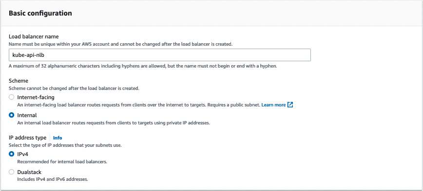
Begin by creating a network load balancer. Internal is an appropriate Scheme since the network is flat.


Create and associate a Target Group. Note that for NLBs in AWS, targets must be registered by IP address.


Registration of nodes could be handled in several automated ways to integrate seamlessly with other cloud mechanics such as Auto Scaling Groups.

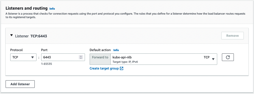
Configure a listener for the load balancer that forwards to the target group.

Install packages and configure Linux system

If nodes have been created without any automation for setup, then it will be necessary to install packages and prepare the system to be a Kubernetes control plane node.

$ echo 1 > /proc/sys/net/ipv4/ip_forward && \

$ echo 1 > /proc/sys/net/bridge/bridge-nf-call-ip6tables && \

$ echo 1 > /proc/sys/net/bridge/bridge-nf-call-iptables && \
modprobe br_netfilter && \
sysctl -p

$ echo br_netfilter > /etc/modules-load.d/br_netfilter.conf && \
systemctl restart systemd-modules-load.service

$ apt update && \
  apt install -y \
    apt-transport-https \
    ca-certificates \
    containerd \
    Curl

$ curl -fsSLo /usr/share/keyrings/kubernetes-archive-keyring.gpg https://packages.cloud.google.com/apt/doc/apt-key.gpg

$ echo "deb [signed-by=/usr/share/keyrings/kubernetes-archive-keyring.gpg] https://apt.kubernetes.io/ kubernetes-xenial main" | sudo tee /etc/apt/sources.list.d/kubernetes.list

$ apt update && \
  apt install -y \
    kubelet \
    kubeadm \
    kubectl && \
  apt-mark hold kubelet kubeadm kubectl

Initialize primary node

Although etcd will be clustered across all control plane nodes, we must first build one node to establish trust for future nodes:

$ kubeadm init -\
-control-plane-endpoint \
"kube-api-nlb-<UNIQUE-ID>.elb.us-east-1.amazonaws.com:6443" \
--upload-certs

Once the first node successfully starts the kubelet, the NLB Target Group should reflect its healthy status.


After initialization, other nodes can be joined as control plane members or as worker nodes.

Your Kubernetes control-plane has initialized successfully!

To start using your cluster, you need to run the following as a regular user:

  mkdir -p $HOME/.kube
  sudo cp -i /etc/kubernetes/admin.conf $HOME/.kube/config
  sudo chown $(id -u):$(id -g) $HOME/.kube/config

Alternatively, if you are the root user, you can run:

  export KUBECONFIG=/etc/kubernetes/admin.conf

You should now deploy a pod network to the cluster.
Run "kubectl apply -f [podnetwork].yaml" with one of the options listed at:
  https://kubernetes.io/docs/concepts/cluster-administration/addons/

You can now join any number of the control-plane node running the following command on each as root:

  kubeadm join kube-api-nlb-<UNIQUE-ID>.elb.us-east-1.amazonaws.com:6443 \
    --token <UNIQUE-TOKEN> \
    --discovery-token-ca-cert-hash sha256:<UNIQUE-HASH> \
    --control-plane --certificate-key <UNIQUE-KEY>

Please note that the certificate-key gives access to cluster sensitive data, keep it secret!
As a safeguard, uploaded-certs will be deleted in two hours; If necessary, you can use
"kubeadm init phase upload-certs --upload-certs" to reload certs afterward.

Then you can join any number of worker nodes by running the following on each as root:

kubeadm join kube-api-nlb-<UNIQUE-ID>.elb.us-east-1.amazonaws.com:6443 \
    --token <UNIQUE-TOKEN> \
    --discovery-token-ca-cert-hash sha256:<UNIQUE-HASH>

Before joining other nodes, follow kubeadm's suggestion and deploy a pod network. We will use Calico in this case.

$ curl https://docs.projectcalico.org/manifests/calico-typha.yaml -o calico.yaml && \
  kubectl apply -f calico.yaml

Initialize secondary node

Once complete, it's time to join additional control plane nodes.

$ kubeadm join kube-api-nlb-<UNIQUE-ID>.elb.us-east-1.amazonaws.com:6443 \
    --token <UNIQUE-TOKEN> \
    --discovery-token-ca-cert-hash sha256:<UNIQUE-HASH> \
    --control-plane --certificate-key <UNIQUE-HASH>

Following the node addition, verify it in the cluster.

$ kubectl get nodes
NAME           	STATUS   ROLES       	AGE 	VERSION
ip-172-31-5-6  	 Ready	control-plane   2m13s   v1.25.0
ip-172-31-57-149   Ready	control-plane   15m 	v1.25.0

Also verify in the Target Group:

Initialize tertiary node

Generate a join command from any node already on the cluster.

$ kubeadm token create --print-join-command

Use the join command to join from a different VPC.

$ kubeadm join kube-api-nlb-<UNIQUE-ID>.elb.us-east-1.amazonaws.com:6443 \
    --token <UNIQUE-TOKEN> \
    --discovery-token-ca-cert-hash sha256:<UNIQUE-ID>
    --control-plane --certificate-key <UNIQUE-KEY>

Verify the node in the cluster.

$ kubectl get nodes
    NAME           	STATUS   ROLES       	AGE	VERSION
    ip-172-30-1-50 	 Ready	control-plane   20m	v1.25.0
    ip-172-31-5-6  	 Ready	control-plane   113m   v1.25.0
    ip-172-31-57-149   Ready	control-plane   126m   v1.25.0

In this case, the node from the secondary VPC has not been added to the network load balancer, although it could be. In the event of a catastrophic loss of the first zone, the Kubernetes API would be unavailable until nodes were added. This is a spare configuration for Kubernetes API. Worker nodes can now be joined in either VPC.

A Note on Certificates

The certificates created during initialization of the first node are only valid for a specific period of time. If these certificates expire or otherwise become invalid, you can generate and upload a new certificate key with these commands.

$ kubeadm certs certificate-key


    $ kubeadm init phase upload-certs --upload-certs --certificate-key=

Nodes joining the control plane after this operation should reference the new key.

Multi-cloud with service mesh

You can extend etcd cluster architecture across cloud providers with network bridging technologies. However, this can rapidly become difficult to manage and a point of failure through complexity. A better option is to implement a service mesh such as Linkerd or Istio.

For our demo, we'll use two clusters, one hosted as GCP GKE and the other as AWS EKS, with context aliases east and west, respectively. These aliases are arbitrary but fit well with project documentation.

Here, a service on the east cluster will be linked to the west cluster and made accessible over the mesh. Although the reality is a bit fuzzier, we can think of west as “primary” and east as “secondary”.

The following will use Linkerd as the service mesh, but the concepts are transferable to Istio too. Both mesh solutions require setting up a cross-cluster (i.e. cross-cloud) trust so that communication between them can be properly encrypted and trusted.

Before administering the clusters, use step-cli to create some pre-trusted certificates.

$ step-cli certificate create identity.linkerd.cluster.local issuer.crt issuer.key --profile intermediate-ca --not-after 8760h --no-password --insecure --ca ca.crt --ca-key ca.key

This will create four files.

ca.crt  ca.key issuer.crt  issuer.key

Install the files on both clusters:

$ linkerd install --crds |
    | tee \
      >(kubectl --context=west apply -f -) \
      >(kubectl --context=east apply -f -)

Once the certificates are installed, they can be referenced as trusted during installation of the mesh on both clusters.

$ linkerd install \
    --identity-trust-anchors-file root.crt \
    --identity-issuer-certificate-file issuer.crt \
    --identity-issuer-key-file issuer.key \
    --set proxyInit.runAsRoot=true \
    | tee \
      >(kubectl --context=west apply -f -) \
      >(kubectl --context=east apply -f -)

> Note: the proxyInit argument may not be required depending on the container runtime of each cluster. proxyInit is required for default EKS and GKE.

K8s clusters handling 10B daily API calls use Kubecost

Verify that the mesh has successfully installed.

$ for ctx in west east; do
    echo "Checking cluster: ${ctx} ........."
    linkerd --context=${ctx} check || break
    echo "-------------"
  done

You should see output similar to:

linkerd-existence
    -----------------
    √ 'linkerd-config' config map exists
    √ heartbeat ServiceAccount exist
    √ control plane replica sets are ready
    √ no unschedulable pods
    √ control plane pods are ready
    √ cluster networks contains all node podCIDRs
    √ cluster networks contains all pods
    
    linkerd-config
    --------------
    √ control plane Namespace exists
    √ control plane ClusterRoles exist
    √ control plane ClusterRoleBindings exist
    √ control plane ServiceAccounts exist
    √ control plane CustomResourceDefinitions exist
    √ control plane MutatingWebhookConfigurations exist
    √ control plane ValidatingWebhookConfigurations exist
    √ proxy-init container runs as root user if docker container runtime is used
    
    linkerd-identity
    ----------------
    √ certificate config is valid
    √ trust anchors are using supported crypto algorithm
    √ trust anchors are within their validity period
    √ trust anchors are valid for at least 60 days
    √ issuer cert is using supported crypto algorithm
    √ issuer cert is within its validity period
    √ issuer cert is valid for at least 60 days
    √ issuer cert is issued by the trust anchor
    
    linkerd-webhooks-and-apisvc-tls
    -------------------------------
    √ proxy-injector webhook has valid cert
    √ proxy-injector cert is valid for at least 60 days
    √ sp-validator webhook has valid cert
    √ sp-validator cert is valid for at least 60 days
    √ policy-validator webhook has valid cert
    √ policy-validator cert is valid for at least 60 days
    
    linkerd-version
    ---------------
    √ can determine the latest version
    √ cli is up-to-date
    
    control-plane-version
    ---------------------
    √ can retrieve the control plane version
    √ control plane is up-to-date
    √ control plane and cli versions match
    
    linkerd-control-plane-proxy
    ---------------------------
    √ control plane proxies are healthy
    √ control plane proxies are up-to-date
    √ control plane proxies and cli versions match
    
    Status check results are √

Now that the mesh is installed, it's time to configure inter-cluster routing. Although conceptually traffic does not leave the mesh — and testing later will demonstrate this — the mechanics of the connectivity are called “routing” because each cluster will implement a gateway service of type LoadBalancer that will be used to communicate across the clusters.

Behind the scenes, Linkerd will use the established mTLS trust to validate traffic requests and permit or deny connectivity.

$ for ctx in west east; do
    echo "Installing on cluster: ${ctx} ........."
    linkerd --context=${ctx} multicluster install | \
      kubectl --context=${ctx} apply -f - || break
    echo "-------------"
  done

After a few moments, verify the connectivity.:

$ for ctx in west east; do
    echo "Checking gateway on cluster: ${ctx} ........."
    kubectl --context=${ctx} -n linkerd-multicluster \
      rollout status deploy/linkerd-gateway || break
    echo "-------------"
  done
  
  Checking gateway on cluster: west .........
  deployment "linkerd-gateway" successfully rolled out
  -------------
  Checking gateway on cluster: east .........
  deployment "linkerd-gateway" successfully rolled out
  ------------- 

At this point, either cluster could be made “primary”. However, from this point forward it will be very important to remember which alias is which. East hosts services locally. West hosts services locally and links to services hosted on east.

To configure the relationship described above, execute this command.

$ linkerd --context=east multicluster link --cluster-name east |
    kubectl --context=west apply -f -

Once successful, also check the multi-cluster status.

$ for ctx in west east; do 
    linkerd --context=${ctx} multicluster check || break
  done
  
  linkerd-multicluster
  --------------------
  √ Link CRD exists
  √ Link resources are valid
      * east
  √ remote cluster access credentials are valid
      * east
  √ clusters share trust anchors
      * east
  √ service mirror controller has required permissions
      * east
  √ service mirror controllers are running
      * east
  √ all gateway mirrors are healthy
      * east
  √ all mirror services have endpoints
  √ all mirror services are part of a Link
  √ multicluster extension proxies are healthy
  √ multicluster extension proxies are up-to-date
  √ multicluster extension proxies and cli versions match
  
  Status check results are √
  
  
  linkerd-multicluster
  --------------------
  √ Link CRD exists
  √ multicluster extension proxies are healthy
  √ multicluster extension proxies are up-to-date
  √ multicluster extension proxies and cli versions match
  
  Status check results are √

> Note: The two clusters are not identical because their purposes have diverged.

This divergence can also be seen in the respective gateway status:

linkerd --context=west multicluster gateways
    CLUSTER  ALIVE	NUM_SVC  	LATENCY
    east 	True       	1     	27ms
    
    linkerd --context=east multicluster gateways
    CLUSTER  ALIVE	NUM_SVC  	LATENCY

Now your multi-cloud service mesh is configured and we can deploy services to it.

Learn how to manage K8s costs via the Kubecost APIs

Deploying a service to each cluster

To demonstrate how our cluster works, let's deploy a service to each cluster.

$ for ctx in west east; do
    echo "Adding test services on cluster: ${ctx} ........."
    kubectl --context=${ctx} apply \
      -n test -k "github.com/linkerd/website/multicluster/${ctx}/"
    kubectl --context=${ctx} -n test \
      rollout status deploy/podinfo || break
    echo "-------------"
  done

> Note: if using aliases other than “east” and “west”, this command will not work as-written because the Linkerd-provided multicluster application assumes “east” and “west” respectively in the path github.com/linkerd/website/multicluster/${ctx}/

With services deployed, configure mirroring for the east service. Linkerd requires that this is configured explicitly.

$ kubectl --context=east label svc -n test podinfo mirror.linkerd.io/exported=true

Reviewing services on the west cluster should now return two entries.


    $ kubectl --context=west -n test get svc -l app=podinfo
NAME       	TYPE    	CLUSTER-IP  	EXTERNAL-IP   PORT(S)         	AGE
podinfo    	ClusterIP   1.2.3.4       	9898/TCP,9999/TCP   54m
podinfo-east   ClusterIP   1.2.3.5       	9898/TCP,9999/TCP   46m

Since packets must be routed between the clusters, it is important that the endpoint IP address on west matches the gateway IP address on east.

$ kubectl --context=west -n test get endpoints podinfo-east \
    -o 'custom-columns=ENDPOINT_IP:.subsets[*].addresses[*].ip'
 
 ENDPOINT_IP
 10.20.30.40
 
 $ kubectl --context=east -n linkerd-multicluster get svc linkerd-gateway \
    -o "custom-columns=GATEWAY_IP:.status.loadBalancer.ingress[*].ip"
 GATEWAY_IP
 10.20.30.40

If this is not the case, then something has gone wrong and the two clusters are not properly linked. Specifically, requests on west for services on east will not route properly and never succeed.

Time to send some requests! Recall that requests must come from pods already on the mesh, therefore exec into west's frontend pod.

$ kubectl --context=west -n test exec -c nginx -it \
    $(kubectl --context=west -n test get po -l app=frontend \
      --no-headers -o custom-columns=:.metadata.name) \
    -- /bin/sh -c "apk add curl && curl http://podinfo-east:9898"

Expect output similar to the output below, specifically look for "greetings from east":

OK: 26 MiB in 42 packages
    {
      "hostname": "podinfo-694fff64fb-hlslg",
      "version": "4.0.2",
      "revision": "b4138fdb4dce7b34b6fc46069f70bb295aa8963c",
      "color": "#007bff",
      "logo": "https://raw.githubusercontent.com/stefanprodan/podinfo/gh-pages/cuddle_clap.gif",
      "message": "greetings from east",
      "goos": "linux",
      "goarch": "amd64",
      "runtime": "go1.14.3",
      "num_goroutine": "9",
      "num_cpu": "2"
    }

You can also verify mesh status with this command.

$ kubectl --context=west -n test get po -l app=frontend -o jsonpath='{.items[0].spec.containers[*].name}'

    linkerd-proxy external nginx internal

The presence of a linkerd-proxy container confirms the pod is on-mesh.

With the routing verified, verify what happens when a pod that isn't on-mesh makes the same request.

$ kubectl --context=west -n test run -it --rm --image=alpine:3 test -- \
    /bin/sh -c "apk add curl && curl -vv http://podinfo-east:9898"

The output is quite different:

If you don't see a command prompt, try pressing enter.

    (1/5) Installing ca-certificates (20220614-r0)
    (2/5) Installing brotli-libs (1.0.9-r6)
    (3/5) Installing nghttp2-libs (1.47.0-r0)
    (4/5) Installing libcurl (7.83.1-r3)
    (5/5) Installing curl (7.83.1-r3)
    Executing busybox-1.35.0-r17.trigger
    Executing ca-certificates-20220614-r0.trigger
    OK: 8 MiB in 19 packages
    *   Trying 10.100.67.184:9898...
    * Connected to podinfo-east (10.100.67.184) port 9898 (#0)
    > GET / HTTP/1.1
    > Host: podinfo-east:9898
    > User-Agent: curl/7.83.1
    > Accept: */*
    >
    * Empty reply from server
    * Closing connection 0
    curl: (52) Empty reply from server
    Session ended, resume using 'kubectl attach test -c test -i -t' command when the pod is running
    pod "test" deleted

Even though the request comes from an on-mesh cluster, and a namespace with on-mesh resources, the pod from which the request is executed is not itself on-mesh and therefore the connection is refused.

What's next?

Services shared between different clusters and cloud providers are great, but if something happens to the primary cluster, problems arise. Service mesh architectures can use traffic spitting to address this problem.

Linkerd uses the service mesh interface (SMI) to implement TrafficSplit. Let's install that dependency.

$ curl --proto '=https' --tlsv1.2 -sSfL https://linkerd.github.io/linkerd-smi/install | sh

    linkerd smi --context=west install --skip-checks | kubectl apply -f -
    
    linkerd smi --context=west check
    linkerd-smi
    -----------
    √ linkerd-smi extension Namespace exists
    √ SMI extension service account exists
    √ SMI extension pods are injected
    √ SMI extension pods are running
    √ SMI extension proxies are healthy
    
    Status check results are √

> Note: The use of skip-checks may be specific to deploying on EKS and is tied to the use of an older Linkerd library; more details are available in issue 8556

By adding a TrafficSplit resource (below) to the west cluster, requests will now be balanced 50-50 with east.

$ kubectl --context=west apply -f - <<EOF
    apiVersion: split.smi-spec.io/v1alpha1
    kind: TrafficSplit
    metadata:
      name: podinfo
      namespace: test
    spec:
      service: podinfo
      backends:
      - service: podinfo
        weight: 50
      - service: podinfo-east
        weight: 50
    EOF

Requesting the frontend service repeatedly will alternate between east and west.

$ kubectl --context=west -n test exec -c nginx -it   $(kubectl --context=west -n test get po -l app=frontend \
	--no-headers -o custom-columns=:.metadata.name)   -- /bin/sh -c "apk add curl && curl http://frontend:8080"


OK: 26 MiB in 42 packages
{
  "hostname": "podinfo-694fff64fb-hlslg",
  "version": "4.0.2",
  "revision": "b4138fdb4dce7b34b6fc46069f70bb295aa8963c",
  "color": "#007bff",
  "logo": "https://raw.githubusercontent.com/stefanprodan/podinfo/gh-pages/cuddle_clap.gif",
  "message": "greetings from east",
  "goos": "linux",
  "goarch": "amd64",
  "runtime": "go1.14.3",
  "num_goroutine": "9",
  "num_cpu": "2"
}

$ kubectl --context=west -n test exec -c nginx -it   $(kubectl --context=west -n test get po -l app=frontend \
	--no-headers -o custom-columns=:.metadata.name)   -- /bin/sh -c "apk add curl && curl http://frontend:8080"


OK: 26 MiB in 42 packages
{
  "hostname": "podinfo-6d889c4df5-s66ch",
  "version": "4.0.2",
  "revision": "b4138fdb4dce7b34b6fc46069f70bb295aa8963c",
  "color": "#6c757d",
  "logo": "https://raw.githubusercontent.com/stefanprodan/podinfo/gh-pages/cuddle_clap.gif",
  "message": "greetings from west",
  "goos": "linux",
  "goarch": "amd64",
  "runtime": "go1.14.3",
  "num_goroutine": "9",
  "num_cpu": "2"

Of course, if the entire west cluster goes down, this still won't help without some extra wrapping from Global Traffic Management (GTM).
Conclusion

There are several options for achieving Kubernetes high availability. Different approaches cater to single-region, multi-region, and multi-cloud use cases, and ensure that organizations can satisfy a wide variety of requirements.

In addition to the technical options, businesses must carefully weigh the costs and benefits of each to find the best fit. Fortunately, thanks to the tremendous flexibility of Kubernetes, there is always flexibility to revisit past decisions as requirements evolve.

Comprehensive Kubernetes cost monitoring & optimization

Continue reading this series